
See the simulation waveform below to understand what I just explained. This way we can add binary numbers of any size without mentioning the value of N specifically. After a pair of numbers are added, just apply reset for at least one clock cycle to show the end of inputs. And the cout output bit is considered to be valid only on the first clock cycle after a high reset.

Bit serial adder vhdl code code#
VHDL Code for X bits Adder (Custom Bits) License. Contribute to adelcsc/VHDLXADDER development by creating an account on GitHub. The cin bit is considered to be valid only on the first clock cycle after a low reset. VHDL Code for X bits Adder (Custom Bits). And in each clock cycle we get the corresponding bit on output s. The design keeps adding the input bits in a serial way, when the reset is not high. Note that, even though this code works as a N-bit adder, we don't have to mention the value of N directly. generate clock with 10 ns clock period. Note that we dont have to mention N here. When i do simulation, the output is always zeros And some times it gives me the same number but with a shift I dont know what is the problem, i tried to put A,B as inout but didnt work as well. Though I have used behavioral level approach to write my code, it should be straight forward to understand if you have the basics right. Vhdl Vs Systemverilog I am writing a VHDL code to impelemt 8 bit serial adder with accumulator.
Bit serial adder vhdl code full#
Therefore, since we are using the behavioral model to write the VHDL code for the full adder, this will be the next statement: architecture Behavioral of FULLADDERBEHAVIORALSOURCE is. In this post, I have used a similar idea to implement the serial adder. If ( reset = 1 ) begin //active high resetĬ = cin //on first iteration after reset, assign cin to c.įlag = 1 //then make flag 1, so that this if statement isnt executed any more.Ĭ = ( a & b ) | ( c & b ) | ( a & c ) //CARRY After declaring the entity and the I/O ports, the next step is to declare the architecture of the VHDL program that we will be using to code the entity. When i do simulation, the output is always zeros And some times it gives me the same number but with a shift I dont know. I am writing a VHDL code to impelemt 8 bit serial adder with accumulator. Output reg s, cout //note that s comes out at every clock cycle and cout is valid only for last clock cycle. vhdl - 8 bit serial adder with accumulator - Stack Overflow. We will be using the if-else logic in this code. Input a, b, cin, //note that cin is used for only first iteration. A complete line by line explanation and the VHDL code for full adder using behavioral architecture method.

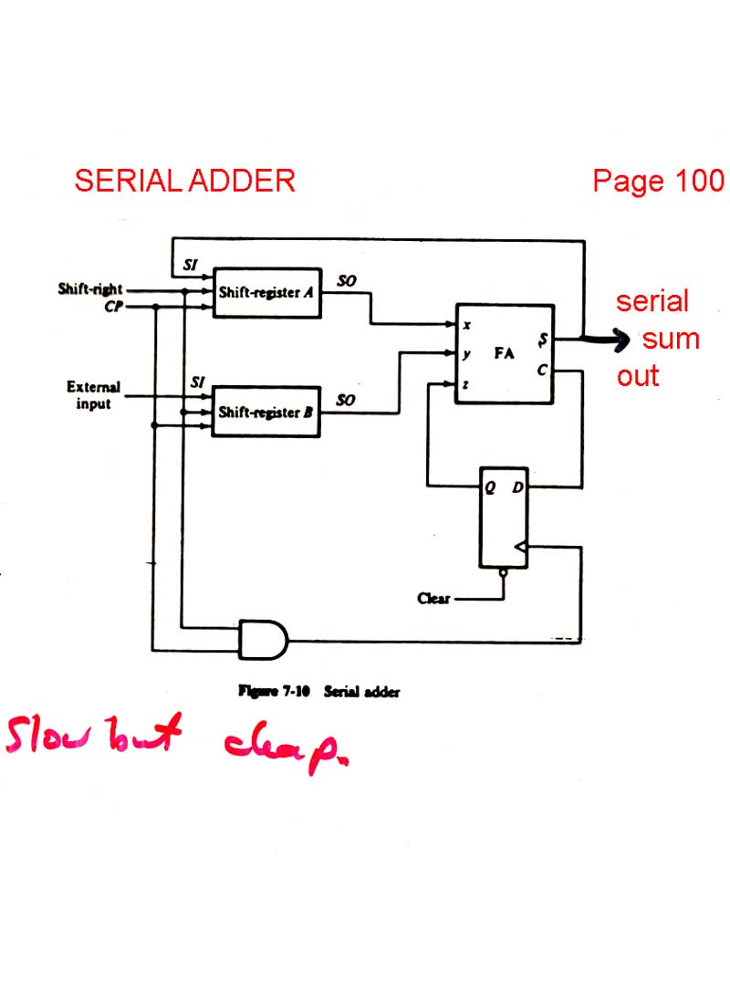
Though I have used behavioral level approach to write my code, it should be straight forward to understand if you have the basics right. This is because two N bit vectors added together can produce a result that is N+1 in size. Note that the carry lookahead adder output (oresult) is one bit larger than both of the two adder inputs. In this post, I have used a similar idea to implement the serial adder. Example 1: Four-Bit Carry Lookahead Adder in VHDL. The D flipflop is used to pass the output carry, back to the full adder with a clock cycle delay. 0 input produce adder output and 1 input produce subtractor output.The above block diagram shows how a serial adder can be implemented. This 1-bit FA can be cascaded to perform multi-bit addition. These are comments to help you better understand what the actual code is doing. NOTE: All lines that start with '-' are not needed. Enter the code as seen below into the empty file. The following is the VHDL code for the 1-bit adder. The design unit multiplexes add and subtract operations with an OP input. To develop VHDL code for design of VHDL Code in different style of modeling To synthesize and simulate the parallel adders Theory: A Full adder is a combinational circuit that adds two one bit numbers along with a carry from the lower stage and produces the sum and the carry as output. Select 'VHDL Source Code' and type in adder1 in the name field, click OK. This example describes a two input 4-bit adder/subtractor design in VHDL.


 0 kommentar(er)
